EV Knowledge Base

Electric Vehicle Insights & News

Discover expert guides, battery diagnostic technical updates, and electric mobility news from New Energy EV.

0%

The 2026 Top Electric Vehicle Motor Maintenance Guide explores the systems that quietly move modern vehicles. Electric vehicle motor maintenance is not simply about replacing engine oil. It involves cooling circuits, bearings, electrical connections, insulation, sensors, software, and high-voltage safety procedures. A faint whine, unusual vibration, or rising motor temperature can reveal trouble before a warning light appears.

John Voelcker, an electric-vehicle industry analyst, offers a practical reminder: “EVs have fewer moving parts, but they still need regular care.” That principle shapes this guide. Fewer mechanical components can reduce routine servicing, but they do not remove the need for inspection. Technicians must examine coolant levels, check for leaks, clean air channels, and review diagnostic data. A small amount of dust near a cooling inlet can matter during a hot summer climb.

Real-world experience also exposes uncomfortable gaps. Some owners rely too heavily on dashboard alerts. Some service schedules remain too general. This guide cannot predict every motor design or driving condition. It may also challenge the belief that quiet operation always means healthy operation.

The following sections explain practical inspection intervals, warning signs, cleaning methods, thermal management, bearing concerns, and professional diagnostic limits. They also distinguish safe owner checks from procedures requiring trained technicians and approved equipment. Good maintenance protects performance, range, and long-term reliability. More importantly, it reduces guesswork when a vehicle behaves differently. Small details matter.
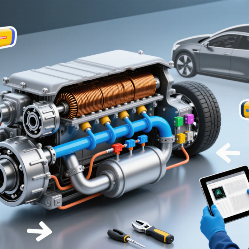
2026 Top Electric Vehicle Motor Maintenance Guide

Classify EV Motors by Topology, Voltage (400–800 V), and Speed (30,000 rpm)

2026 Top Electric Vehicle Motor Maintenance Guide

Classify EV motors by topology, voltage, and speed before planning maintenance. Common topologies include permanent-magnet synchronous, induction, switched-reluctance, radial-flux, and axial-flux designs. Each has different heat paths, bearing loads, and inspection points. Topology changes everything.

A 400-volt motor system may use different insulation and cooling practices than an 800-volt system. Always verify the measured bus voltage, insulation condition, and discharge time through approved service procedures. Wear rated protective equipment, isolate the vehicle, and confirm zero energy with a suitable meter. Do not trust a dashboard warning alone. That shortcut can fail.

Speed adds another risk. Motors reaching 30,000 rpm need precise rotor balance, clean cooling channels, and strict bearing inspection. Listen for a changing whine during controlled testing. Check vibration data, resolver signals, coolant flow, and shaft seals. Fine metallic dust near the housing deserves attention. It may indicate wear, not harmless residue.

In field maintenance, I record temperature before and after load testing. A rising temperature gap often reveals restricted cooling or weakened insulation. However, temperature alone can mislead. Ambient conditions and software limits matter too. I once treated a noise as a bearing fault, but loose mounting hardware caused it. Recheck basic causes. Use the service limits for the exact motor, because similar-looking units can require different clearances, lubricants, and test voltages.

Apply ISO 6469-3 High-Voltage Isolation Before Any Motor Service

2026 Top Electric Vehicle Motor Maintenance Guide

Electric vehicle motor service must begin with high-voltage isolation. ISO 6469-3:2021 addresses protection against electric shock in road vehicles. Its principles support controlled isolation, insulation, and protection from hazardous voltage. The International Energy Agency reported over 17 million electric cars sold globally in 2024. That growth increases the number of technicians handling energized systems.

Before opening a motor housing, review the vehicle’s service procedure and identify every high-voltage source. Park securely, switch off the vehicle, remove the service disconnect, and apply an approved lockout device. Wear voltage-rated gloves, face protection, and insulated footwear. Wait for the documented capacitor discharge period. Then test for absence of voltage with a verified meter, before and after testing a known live source.

Do not trust a dark dashboard.

Inspect the meter leads, glove condition, isolation barriers, and warning labels. Check the motor casing and orange cables for abrasion, moisture, or crushed insulation. An insulation resistance test may reveal damage that visual inspection misses, but use the specified test voltage and limits. The IEA also notes that EV deployment is expanding rapidly, while repair skills and charging infrastructure must keep pace. That gap deserves attention.

A disconnected plug does not prove a safe circuit. It may only prove one step was completed. Technicians should record isolation time, test results, and faults before work begins. Procedures can feel repetitive, yet skipping one verification can turn routine maintenance into a serious electrical event.

Inspect Coolant, Oil, Seals, and Bearings for 90–95% Efficiency Targets

Electric motor efficiency often sits between 90% and 95% under suitable operating conditions. The U.S. Department of Energy identifies electric-drive systems as capable of exceeding 90% peak efficiency. However, peak figures can mislead. Heat, contamination, and poor lubrication quickly reduce real-world performance.

Check the coolant circuit during every scheduled service. Measure fluid level, inspect hoses, and look for dried residue near fittings. A blocked passage can raise winding temperatures within minutes. Use the specified coolant chemistry. Mixing fluids is a small mistake with expensive consequences. The 2025 International Energy Agency Global EV Outlook reported more than 17 million electric cars sold globally in 2024. More vehicles mean more motors operating outside laboratory conditions.

Oil-filled drive units need careful inspection. Check oil color, metallic particles, odor, and quantity. A magnetic drain plug can reveal early gear or bearing wear. Inspect shaft seals for dampness, especially after thermal cycling. A seal may appear dry when cold, then leak after a long climb. Bearings deserve equal attention. Listen for a rising hum, feel for vibration, and compare temperature readings across repeated routes.

Do not trust one measurement. I have found that a clean coolant level can hide restricted flow. Maintenance records should connect temperature, vibration, oil condition, and mileage. The IEC 60034-30-1 efficiency framework shows why small losses matter, but field conditions remain less predictable. That gap deserves honest review.

Measure Insulation, Phase Balance, and Inverter Faults Using IEC 60034

In 2026, electric vehicle motor maintenance depends on disciplined measurement, not guesswork. IEC 60034 provides a useful framework for rotating-machine testing. Before testing, isolate the motor, discharge the DC bus, and record winding temperature. Measure insulation resistance between windings and ground with a suitable insulation tester. Temperature changes can distort comparisons. A declining trend matters more than one impressive reading.

Check phase resistance and inductance across all winding pairs. Large differences may indicate loose joints, partial shorts, or uneven connections. During operation, compare phase currents under the same load. Voltage imbalance can create excess heating and vibration. Inspect inverter fault logs beside these measurements. Overcurrent, ground-fault, overtemperature, and encoder-related alarms may point to different causes. Do not replace the inverter immediately. The motor cable, connectors, cooling path, and resolver circuit deserve inspection too.

Tips: Use calibrated instruments and document every result. Keep test voltage and timing consistent. Never test a connected inverter. I once trusted a single insulation reading and missed a temperature effect. That was poor practice. A clean result is not permanent proof. Recheck after water exposure, overheating, unusual noise, or repeated trips. Follow the applicable IEC 60034 requirements, equipment instructions, and site safety procedures.

2026 Top Electric Vehicle Motor Maintenance Guide

Insulation resistance, phase balance, and inverter fault trend measured in accordance with an IEC 60034-based maintenance procedure.

Representative six-month measurements for a low-voltage three-phase traction motor: insulation resistance was measured at 500 V DC, phase resistance imbalance was calculated at 20°C, and inverter faults were taken from the drive event log. The downward insulation trend and rising phase imbalance indicate that further inspection should be scheduled. IEC 60034 does not define one universal pass/fail limit for every motor, so results should be compared with the motor manufacturer’s service limits, test history, and applicable site procedures.

Check Class H Windings (180°C) and Bearing Vibration After Reassembly

2026 Top Electric Vehicle Motor Maintenance Guide

Class H windings carry a 180°C insulation rating, not a recommended operating temperature. After reassembly, verify the winding condition with documented insulation resistance and phase-balance tests. Use calibrated instruments and follow the motor manufacturer’s service limits. A dry, clean terminal area matters. Small moisture traces can distort readings.

Inspect the end windings for loose ties, damaged varnish, or contact marks. Confirm that leads are routed away from rotating parts. Tighten terminals with the specified torque, then record the value. Do not rely on feel. It is easy to over-tighten a small fastener and weaken the connection.

Bearing vibration needs a baseline. Measure radial and axial vibration before the first run, during low-speed operation, and at normal speed. Mount the sensor at the bearing housing, not on a thin cover. Listen for roughness, pulsing, or a rising whine. These details can reveal misalignment, preload errors, contamination, or uneven seating. Check temperature alongside vibration, because vibration alone can mislead. A stable reading after ten minutes is not proof of a perfect repair. Recheck it after a controlled run-in period. The difficult part is often not finding a high value, but noticing a gradual change. One practical mistake deserves attention: technicians may compare readings from different sensor positions. That weakens the trend and creates false confidence. Keep the same measurement points, speed, load, and recording method each time.

2026 Top Electric Vehicle Motor Maintenance Guide – Check Class H Windings (180°C) and Bearing Vibration After Reassembly
Maintenance Area Inspection Point Recommended Method or Instrument Reference Value or Acceptance Criteria Recommended Timing Action if Out of Range
Electrical and Thermal Verification
Insulation thermal class Confirm the winding insulation system is rated Class H. Review the motor nameplate, repair records, insulation-system documentation, and temperature-rise design data. Class H insulation has a maximum operating temperature of 180°C under the IEC 60085 classification system. Before commissioning and after rewinding or major repair. Do not operate the motor at the intended load until the insulation rating and temperature-rise limits are verified.
Winding resistance Compare phase-to-phase resistance and identify loose connections, damaged conductors, or unequal coils. Use a calibrated low-resistance ohmmeter; allow the winding to reach a stable temperature and record the temperature. All phase readings should be closely balanced and compared with the motor manufacturer’s repair data. Correct readings for winding temperature when applicable. After reassembly, after terminal work, and during scheduled overhaul. Inspect busbar joints, crimped connections, soldered joints, and coil leads. Repeat the test after the winding reaches a uniform temperature.
Insulation resistance Check winding-to-ground insulation and, where applicable, phase-to-phase insulation. Use an insulation-resistance tester at the voltage specified by the motor manufacturer and applicable safety procedure. Record the measured value, test voltage, winding temperature, and test duration. Use the manufacturer’s minimum value; a common maintenance practice is to trend readings rather than rely on one result. Before first energization, after cleaning or moisture exposure, and after major repair. Dry and clean the winding, isolate connected electronics, and retest. Investigate any rapid downward trend.
Polarization index Evaluate insulation condition by comparing the 10-minute and 1-minute insulation-resistance readings. Perform a timed insulation-resistance test when permitted by the motor and inverter manufacturer. PI = insulation resistance at 10 minutes ÷ insulation resistance at 1 minute. Interpret the result with the insulation system, contamination level, temperature, and applicable standard. During major overhaul or when insulation resistance is questionable. Investigate moisture, contamination, surface tracking, or insulation aging before energizing.
Winding temperature sensing Verify resistance temperature detectors, thermistors, or other embedded sensors. Check sensor resistance or signal output against the sensor specification and verify wiring continuity. Sensor readings must be plausible, stable, and consistent across phases. The Class H limit of 180°C is not a normal operating target; the application temperature limit must be lower and manufacturer-defined. After reassembly and during commissioning. Repair wiring, replace damaged sensors, and confirm inverter protection thresholds before operation.
Phase sequence and electrical symmetry Confirm correct phase identification and balanced electrical behavior during a controlled run. Use a phase-sequence tester and measure voltage/current with suitable true-RMS instruments. Phase sequence must match the control system. Current imbalance should be investigated rather than accepted as normal; compare with the motor and inverter specifications. After terminal reconnection, inverter replacement, or motor installation. Check phase leads, resolver or position feedback, inverter settings, and connection torque.
Bearing, Rotor, and Mechanical Checks
Bearing installation Check bearing seating, shaft fits, housing fits, seals, spacers, and retaining components. Visual inspection, dimensional inspection, correct fitting tools, and assembly records. Bearing rings must be fully seated without brinelling, scoring, contamination, or unintended axial preload. Every time a bearing is removed or replaced. Replace damaged bearings or components. Correct the fit or assembly method before rotating the motor.
Lubrication Verify grease type, quantity, compatibility, and contamination control. Review the lubrication specification and measure or control the applied quantity during assembly. Use only the lubricant specified for the bearing speed, temperature, seals, and application. Avoid mixing incompatible greases. At bearing replacement and according to the motor maintenance schedule. Remove incompatible or contaminated lubricant where required and relubricate using the approved procedure.
Post-reassembly bearing vibration Measure vibration at the drive-end and non-drive-end bearing housings in horizontal, vertical, and axial directions. Use a calibrated vibration analyzer or accelerometer. Measure overall velocity in mm/s RMS and record speed, load, direction, and sensor location. Use ISO 20816 evaluation zones and the motor manufacturer’s limits. As a practical screening guide for many small or medium industrial machines, overall vibration below approximately 2.8 mm/s RMS is commonly considered acceptable, but it is not a universal EV-motor limit. At no-load or controlled-load commissioning, then after the initial run-in and at scheduled intervals. Stop and investigate increasing or excessive vibration. Check balance, alignment, bearing seating, rotor clearance, looseness, gear mesh, and structural resonance.
Vibration trend Compare the new measurement with the baseline obtained after successful reassembly. Use the same sensor locations, measurement directions, speed, load, and bandwidth for each measurement. A stable trend is more important than a single reading. A significant increase from the established baseline requires investigation even when the absolute value remains below a general screening limit. At each scheduled inspection and after abnormal noise, overheating, or impact. Repeat the measurement to confirm the result, then perform spectrum analysis and mechanical inspection.
Bearing temperature Check bearing housing temperature and temperature rise after the motor reaches thermal stability. Use a calibrated contact probe, infrared instrument with correct emissivity settings, or embedded sensor. No universal temperature limit applies to every bearing. Compare with the bearing, grease, motor, and manufacturer’s specified operating limits and trend the temperature over time. During commissioning, after run-in, and during routine condition monitoring. Check lubrication quantity, preload, alignment, load, cooling, and bearing condition. Shut down if temperature rises rapidly.
Rotor-to-stator clearance Confirm that the rotor turns freely without rubbing or abnormal drag. Manual rotation where safe, endplay measurement, inspection marks, and manufacturer-approved clearance checks. No contact marks, scraping noise, or abnormal mechanical resistance should be present. Clearance must remain within the motor design specification. After rotor installation and before electrical energization. Disassemble and inspect bearings, end brackets, rotor position, foreign objects, and housing distortion.
Shaft grounding and bearing-current protection Verify shaft grounding or insulated-bearing arrangements used to control inverter-induced bearing currents. Inspect grounding components and measure continuity or resistance according to the motor design. Grounding paths must be clean, secure, and electrically continuous where specified. Do not bypass insulated-bearing requirements. After reassembly, grounding work, or inverter changes. Clean contact surfaces, restore the specified grounding path, and inspect bearings for electrical fluting.
Assembly, Commissioning, and Records
Fastener tightening Check end-bracket, housing, terminal, sensor, and mounting fasteners. Use a calibrated torque wrench and follow the applicable assembly sequence. Torque values must follow the motor or component specification. Record the actual torque where required by the maintenance procedure. After every major disassembly and before commissioning. Correct loose or over-tightened fasteners and inspect for thread damage, distortion, or loss of bearing alignment.
Alignment and mounting Check motor-to-load alignment, mounting flatness, soft foot, and coupling condition. Use dial indicators or laser alignment equipment and inspect mounting surfaces. Meet the coupling and motor manufacturer’s angular, parallel, soft-foot, and mounting tolerances. After installation, coupling work, or foundation repair. Correct soft foot, shimming, mounting distortion, coupling wear, and alignment errors before full-load operation.
Controlled run-in Observe startup current, speed feedback, sound, vibration, and temperatures during a controlled no-load or partial-load run. Use the inverter diagnostic system, vibration analyzer, temperature sensors, and a commissioning checklist. All values should stabilize without abnormal noise, rapid temperature rise, unexpected current imbalance, or increasing vibration. Immediately after reassembly and before returning to service. Stop the test and correct the first abnormal condition identified; do not continue operation to “test” a suspected mechanical fault.
Maintenance record Document measurements, instrument identification, test conditions, and corrective actions. Use a controlled digital or paper maintenance form. Record motor identification, operating hours, winding temperature, insulation results, vibration values by direction, bearing temperature, torque checks, and technician/date. Every inspection, repair, and commissioning event. Do not close the maintenance task until missing readings, deviations, and approvals are resolved.
Note: Acceptance limits for electric vehicle traction motors depend on motor construction, rotor speed, inverter operation, bearing type, cooling system, mounting arrangement, and the vehicle manufacturer’s service specification. The values shown above are maintenance guidance and should be used together with the applicable motor documentation, safety procedures, and relevant IEC or ISO standards.

FAQS

How should electric vehicle motors be classified before maintenance?

Classify them by topology, voltage, and maximum speed. Common designs include permanent-magnet, induction, reluctance, radial-flux, and axial-flux motors. Each design has different cooling paths, bearing loads, and inspection points. Topology changes everything.

What safety steps are needed before opening a motor housing?

Switch off the vehicle and secure it on stable ground. Remove the service disconnect and apply an approved lockout device. Wait for the documented capacitor discharge period. Wear rated gloves, face protection, and insulated footwear. Then test for zero voltage with a verified meter. Do not trust a dark dashboard.

How do 400-volt and 800-volt systems differ during service?

They may use different insulation, cooling, and testing practices. Confirm the actual bus voltage before choosing test equipment. Check insulation condition and discharge time through the approved procedure. Never assume two similar motors share the same test voltage. That assumption can fail.

What should be inspected on a motor reaching 30,000 rpm?

Check rotor balance, bearing condition, cooling channels, and shaft seals. Review vibration data and listen for changing sounds during controlled testing. Inspect resolver signals and coolant flow. Fine metallic dust near the housing may indicate wear. It is not always harmless residue.

How can technicians evaluate insulation and winding condition?

Measure insulation resistance between windings and ground with suitable equipment. Record winding temperature during testing. Compare phase resistance and inductance across every winding pair. Large differences may indicate loose joints or partial shorts. One clean reading is not permanent proof.

How should inverter faults be investigated?

Compare fault logs with phase currents, voltage balance, and temperature data. Overcurrent, ground-fault, overtemperature, and encoder alarms suggest different causes. Inspect cables, connectors, cooling paths, and resolver circuits. Do not replace the inverter immediately. The fault may be elsewhere.

What temperature information is useful during motor maintenance?

Record temperature before and after controlled load testing. A growing temperature difference may reveal restricted cooling or weakened insulation. Ambient temperature and software limits can distort the result. Temperature alone can mislead. Use repeated measurements.

What basic mistakes can cause incorrect motor diagnoses?

Check loose mounting hardware before blaming a bearing. Inspect moisture, crushed insulation, abrasion, and connector damage. Keep test voltage, timing, and instrument calibration consistent. Record isolation times, readings, and faults. I once misread a noise. The mounting hardware was loose.

Conclusion

Electric vehicle motor maintenance requires a structured approach that begins with identifying the motor’s topology, operating voltage, and maximum speed, especially in systems ranging from 400 to 800 volts and reaching up to 30,000 rpm. Before any inspection or repair, technicians should follow ISO 6469-3 procedures to confirm high-voltage isolation and prevent electrical hazards. Regular checks of coolant flow, lubrication oil, seals, and bearings help support efficiency targets of approximately 90–95% and reduce the risk of overheating or mechanical wear.

After servicing, electrical condition should be verified through insulation resistance testing, phase-balance measurements, and inverter fault analysis in line with IEC 60034 principles. Class H windings should be assessed for thermal stress up to 180°C, while bearing vibration should be measured after reassembly to identify imbalance, misalignment, or looseness. Careful documentation of all findings ensures reliable performance, safer operation, and longer motor service life.

Isabelle

Isabelle

Isabelle is a dedicated marketing professional with a robust understanding of our core business and a passion for driving strategic growth. With an extensive background in marketing and product expertise, she plays a pivotal role in crafting insightful content for our company blog, ensuring that......
Ask New Energy